MS-1LF Instructions
The MS-1LF shield is similar to Twinleaf's other shields except for its ferrite endcaps encased in delrin. Specific construction details can be found here. The ferrite endcaps are very sensitive to scratches and gouges. For the best handling practice, follow these Do's and Do Not's:
DO
- maintain a secure hold on the inner ferrite cap when handling, and carry plastic down if possible.
- lay the endcaps plastic side down for storage when working inside the shield
- handle all ferrite components gently, especially when installing or removing endcaps.
DO NOT
- hold the endcaps by the plastic alone. The ferrite piece is not permanently affixed and can fall out if not held in place
- lay the endcaps ferrite side down on a horizontal surface. The ferrite might get scratched, or slip out, drop, and break in this orientation
- allow the ferrite contact surfaces to become scratched or gouged. This will render the shield less effective.
Setting Up
Setting up an MS-1LF shield is very similar to the setup for all shields except for the handling of the ferrite. Please note that in order for the shielding to work, the ferrite pieces must make smooth contact with one another. If an endcap is misaligned, or if a piece becomes scratched or gouged, the inner shielding will be less effective. The following instructions describe how to install and remove the endcaps of your ferrite shield
Endcap Installation
-
Using a lint-free cloth and ethanol, gently wipe the ferrite surfaces that will make contact. This includes the ends of the inner cylinder and the outside rim of the endcaps.
-
Place the endcap in position, inside of the shield. The slot should be placed towards the bottom of the shield.
-
Gently slide the endcap into place. Make sure that it is correctly aligned and makes good contact with the inner ferrite shield.
-
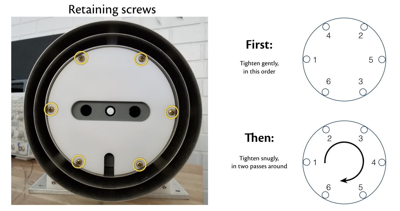
Keeping one hand on the endcap to secure it in place, position the six holding screws as shown in the figure below. Tighten the screws in the sequence shown; first in a star pattern, and then iteratively in a circle. Tighten the screws slowly to ensure that uniform contact is made between the inner ferrite shields.
-
Tighten only until the endcap is held firmly in place; do not strip the inner plastic with too much tension.
-
Place the smallest metal endcap in position. Align the slots near the bottom, and slide it onto the main shield body. Repeat this process for the other two outside endcaps.
Endcap Removal
-
Remove the three outer metal shields by gently sliding them, one at a time, off of the main shield body. Set them aside.
-
Keeping one hand on the endcap for stability, remove the six outer screws in the reverse order of installation (see the figure above).
-
With the retaining screws removed, gently slide the endcap outwards. At the end, tip the top backwards, so that the ferrite side is on top of the plastic. Remove the endcap.
-
If you wish to set the endcap aside for prolonged periods of time, remove the extraction screws and place the endcap plastic-down on a flat surface.
Sample Mounting
The delrin stage at the center of the shield is tapped with a number of threaded holes. This allows for samples, wiring, etc. to be secured to the stage. Do not use magnetic fasteners such as stainless steel or nickel - Twinleaf recommends the use of nylon or brass screws. The generated fields made by the internal coils are most uniform in the 2 cm region at the center of the shield. This does not align with the stage surface, and sample mountings should be adjusted accordingly.
The stage can be removed if necessary by removing the four retaining screws near the outer corners. These screws also maintain the alignment of the internal field coils, so it is best practice to put the screws back in after removing the stage.
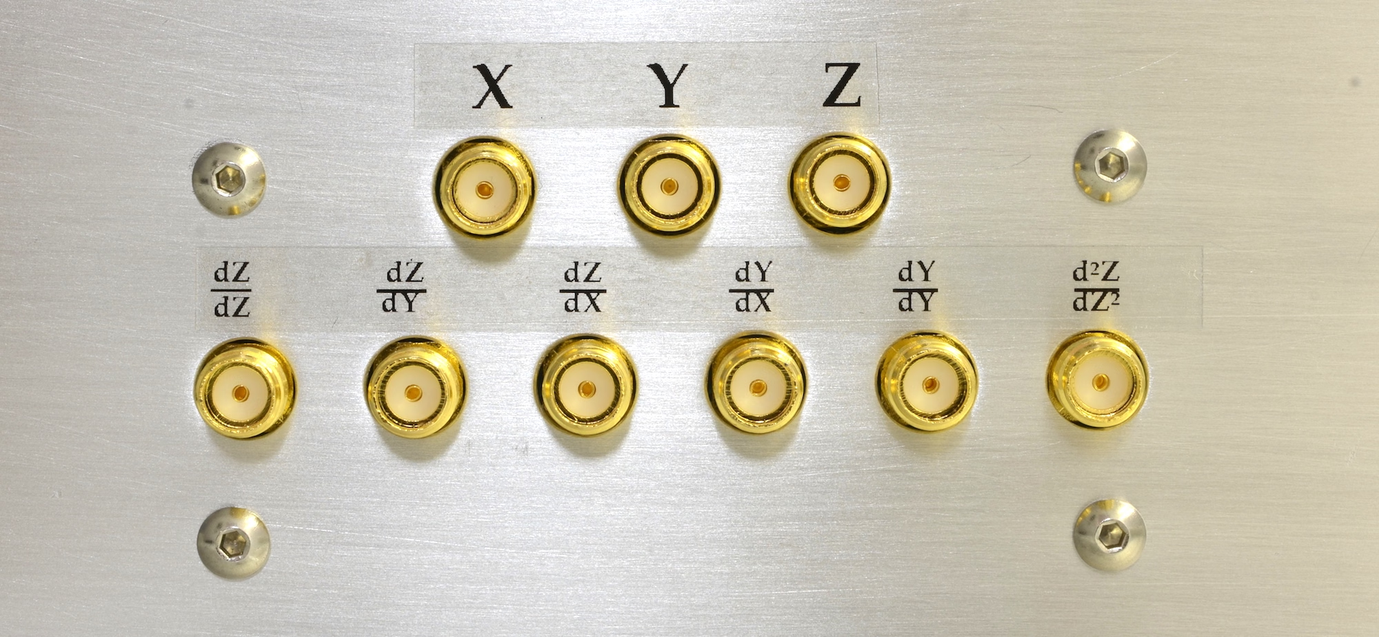
Generating Fields Inside Your Shield
The internal field coils can be accessed through the front control board on the shield. It will look like the figure below. To create fields in a particular direction, connect a current supply to the pin labelled with the desired direction. Orientations for the XYZ axes are shown by black stickers on the shield's outermost layer. The field strength can be adjusted using your current supply.