Getting Started with Twinleaf Magnetic Shielding
Twinleaf magnetic shields are designed to provide high shielding factor and high field uniformity. The following document provides a background and guide for shield setup and use. For specific instructions related to our ferrite shields (MS-1LF), visit our MS-1LF Instructions page
Design
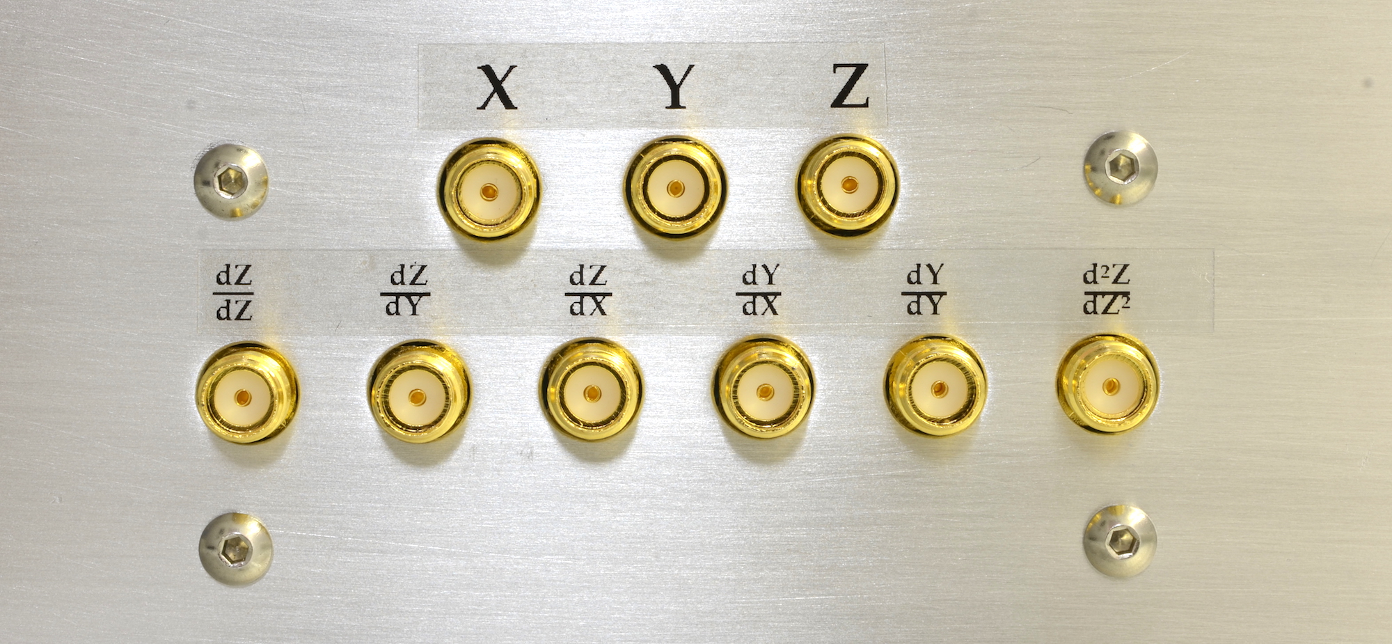
Each shield is comprised of several layered metal cylinders. The metal used to create these cylinders has a high permeability µ thanks to the high nickel content in the alloy. When formed into cylindrical shells, the magnetic material channels external fields through the shell material, thereby shielding the inner volume. Each shield also contains internal field coils for the generation of known fields inside of the shield. These coils are capable of creating tunable, homogenous, orthogonal XYZ fields. Orientations for these generated fields are shown by black stickers on the shield's outermost layer. Three primary XYZ coils and five gradient coils are provided.
Be gentle!
The shielding metal performance degrades when it is subject to stress, thermal extremes, shocks, dents, and bends. Be very gentle when handling and storing the shield components. To limit shocks during shipping, the magnetic shields are packed with multiple layers of foam that will need to be removed before use.
Setting Up
To place equipment inside the magnetic shields, the end caps may be removed. Each end cap has a pair of nylon cord pulls to help pull them off the shield body. On each end cap there is a small slot. To put the endcaps back on the shield, hook these edges under the lower edge of the shield body, push the top edge over the shield body, and them slide evenly into place. Make sure that each end cap is flush against the body of the shield.
Sample Mounting
The delrin stage at the center of the shield is tapped with a number of threaded holes. This allows for samples, wiring, etc. to be secured to the stage. Do not use magnetic fasteners such as stainless steel or nickel - Twinleaf recommends the use of nylon, polypropylene, aluminum, or titanium screws. The generated fields made by the internal coils are most uniform in the 2 cm region at the center of the shield. Detailed plans and models are available to the designer.
The stage can be removed if necessary by removing the four retaining screws near the outer corners. These screws also maintain the alignment of the internal field coils, so they should be replaced after removing the stage.
Generating Fields Inside Your Shield
The internal field coils can be accessed through the front control board on the shield. It will look like the figure below. To create fields in a particular direction, connect a current supply to the pin labelled with the desired direction. Orientations for the XYZ axes are shown by black stickers on the shield's outermost layer. The field strength can be adjusted using your current supply.
For more information, check out our Magnetic Shield FAQ